Backplane Development for VPX, OpenVPX and SOSA Aligned Board Payloads
Backplane Development for VPX, OpenVPX and SOSA Aligned Board Payloads
4 MIN READ
SHARE:
Backplane development is arguably the most important step when creating a deployable integrated system for defense applications. VPX, OpenVPX and SOSA systems take form in a development to deployment progression where functional system elements are identified and brought together in an open frame test platform before moving on to the field deployable chassis.
VPX, OpenVPX and SOSA Architectures and the Impact to Backplane Design
Backplanes, like plug-in-cards (PICS)*, are differentiated by architecture. Going forward, SOSA will be predominant in defense applications. While chassis are largely agnostic regarding architecture, backplanes are not. They either support a particular architecture and the associated PICS, or they do not. It is important to understand that the design methodology, and the test and development processes, are the same for all three architectures and that one backplane design may support PICs from all 3 architectures.
Defining the Top-Level System Requirements
During the backplane development process, system level requirements are identified, including I/O signal types, signal speeds and data flow rates. These may include 10, 40 and 100 Gb Ethernet, RF or optical I/O. Next, computational needs are distinguished. The necessary data processing and data collection requirements are determined and the PIC selection begins. This may include CPU, GPU, FPGA, networking and storage functions.
After PIC selection is complete, slot-to-slot data flows and data rates are mapped out on the backplane for the data and control planes. This is also done for expansion plane, power distribution and system management requirements. In short, all board-to-board, and board-to-external I/O interconnects that are necessary to support the application, are determined and eventually tested at the system level.
Building the Backplane Profile
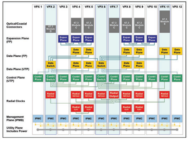
VPX** PICs have a module profile. This is what makes them distinct. This profile maps pin assignments, including pin locations and I/O signal types that are located on the connector. The backplane is a combination of the module profiles associated with the selected PICs and the connectivity between them.
The process of defining PIC interconnectivity through the backplane, results in an interconnect map known as the backplane profile. It is the backplane profile that enables the PICs and their related functionality to perform the tasks required of the application system.
The process of defining PIC interconnectivity through the backplane, results in an interconnect map known as the backplane profile. It is the backplane profile that enables the PICs and their related functionality to perform the tasks required of the application system.
Serial Connectivity
The parallel bus structure and other aspects of VME and cPCI architectures have made off-the-shelf backplanes possible for most board sets. As a serial point-to-point architecture, VPX requires some level of customization to the backplane from application to application. VPX also offers multiple options for rear connectivity for optical and RF I/O. The added system design complexity brought on by VPX is easily offset by huge gains in signal speeds and increased flexibility in design.
The evolution from VPX to OpenVPX to SOSA, has successfully addressed the complexity issue. The SOSA Technical Standard has reduced and standardized the number of module profiles. This has begun to pave the way for off the shelf standard backplane profiles in the future (or at least a set of commonly used backplane profiles).
New backplanes must still be designed. As backplane profiles continue to grow, new designs can leverage aspects of existing designs. Typically, no two VPX backplanes are exactly alike; however, evolving applications and their commonality will likely pave the way towards standard backplane profiles.
Building the Test Backplane
Final backplane fabrication should begin after the profile is tested and locked in to ensure that signal flow / signal integrity and system operation meet the application requirements. This creates the need for well-designed development platforms that support system realization. VPX development chassis must enable open access to the PICs under test, as well as 5V and 12V payload power options. The chassis needs to be easily configurable for air cooled or conduction cooled PIC usage. A development backplane must also be included.
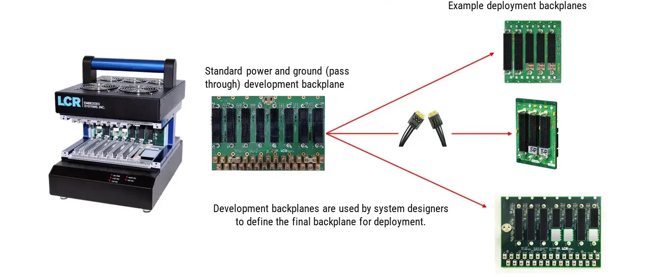
A basic development backplane (also known as an uncommitted or power and ground backplane) for VPX, OpenVPX and SOSA PICs have no embedded slot-to-slot connections. They are essentially blank canvases that allow developers, by way of commercial slot-to-slot cabling systems, to lay out the necessary backplane profile and establish applicable data flows.
As the SOSA effort evolves, new development backplanes are being introduced, including the latest PIC profiles identified in the SOSA Technical Standard. These reference backplanes, that support the slot-to-slot connections intended by SOSA, can be used as configured or can serve as a development springboard where a majority of the interconnectivity is already in place. Whether the development process starts with an uncommitted backplane or a reference backplane, the final design must then be fabricated.
Backplane Cable Connection System
To create the required slot-to-slot connectivity, VPX backplane cabling systems are used. The cables act in place of the slot-to-slot traces that will eventually be designed into the backplane. They allow system level testing, data flow analysis and all slot-to-slot communications before fabricating the deployment backplane.
Connections are made via the rear slots of the backplane, while the payload PICs are inserted in the corresponding front backplane slots to be connected. Cable sets can be configured to create ultra-thin pipes, thin pipes and fat pipes (UTP, TP and FP) that establish the data plane, control plane and expansion plane connections, as well as custom slot-to-external I/O connections.
VPX/SOSA Backplane Cabling Systems
VPX / SOSA cabling systems
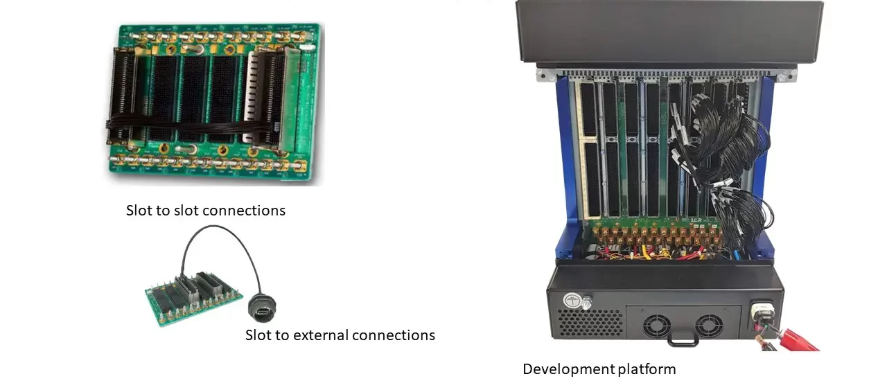
Currently cable systems enable PCIe Gen3 and 10GbE 40GBASE-KR4 (4 lanes = 40Gbps) signal speeds. Single ended and differential pair signals can be used in the VPX architecture. The image below shows examples of cables in place, including simple slot-to-slot connections, slot-to-external I/O and a cable set installed in the backplane of an LCR DK3 open frame development chassis.
Backplane Development Stages
Currently cable systems enable PCIe Gen3 and 10GbE 40GBASE-KR4 (4 lanes = 40Gbps) signal speeds. Single ended and differential pair signals can be used in the VPX architecture. The image below shows examples of cables in place, including simple slot-to-slot connections, slot-to-external I/O and a cable set installed in the backplane of an LCR DK3 open frame development chassis.
The SOSA Technical Standard Opens Doors
The SOSA Technical Standard opens the door to a more streamlined realization process for backplanes and deployable integrated systems. A basic understanding of the development process is essential. New development chassis, backplanes and cabling systems are essential tools to be used in that effort.
*The term board has been replaced with ‘plug-in-card’ or PIC. This language was established in the SOSA Technical Standard.
**The term VPX applies here to OpenVPX and SOSA as well.